Exercise 4 : Materials and Effects
Description
In this exercise, you will play the role of a kitchen designer by creating several materials using both the Unity material shaders, and the Shader Graph system.
In case of any problems, please see the FAQ and the Problems and Solutions. If your problem is not listed, contact me by e-mail (Tomas Polasek : ).
Instructions
This exercise takes you through the process of material creation and utilization:
- Creating Unity Materials and using the builtin lighting models
- Using the Shader Graph to implement a simple procedural wood material
- Personalizing the kitchen model
Download the project template from the Materials section and follow the same general procedure as in the case of previous exercises. In case of problems, see the information in the second exercise (use the 3D editor mode).
Initially, the scene may appear turquoise. This signals that Unity is processing materials and should pass after a short while. Progress should be reported in the bottom right corner of the Unity Editor. After setting up the project and running it, you should be able to walk through the kitchen by using the standard first person control scheme (WASD + Mouse).
Using Unity Materials
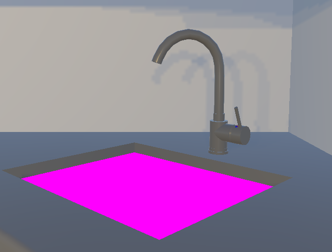
By default, Unity supports several material types, which you will find quite useful in your future projects. After looking through the kitchen scene, you should notice that something is wrong with the kitchen sink. Unity has several special colors with respect to shaders and materials which signify specific situations. Turquoise color represents a material which is not yet fully loaded - usually, this is fixed by just waiting a moment. Similarly, the bright pink color of the sink signifies, that there is a problem with its material. Select the sink and see that indeed, inside the inspector component Mesh Renderer -> Materials -> Element 0, we have no material selected! Now, let us remedy this problem.
Navigate to Assets/Materials/Kitchen/ and create a new material through the context menu Create -> Material. Name the newly created material Sink and display its details in the Inspector. You should see the following information:
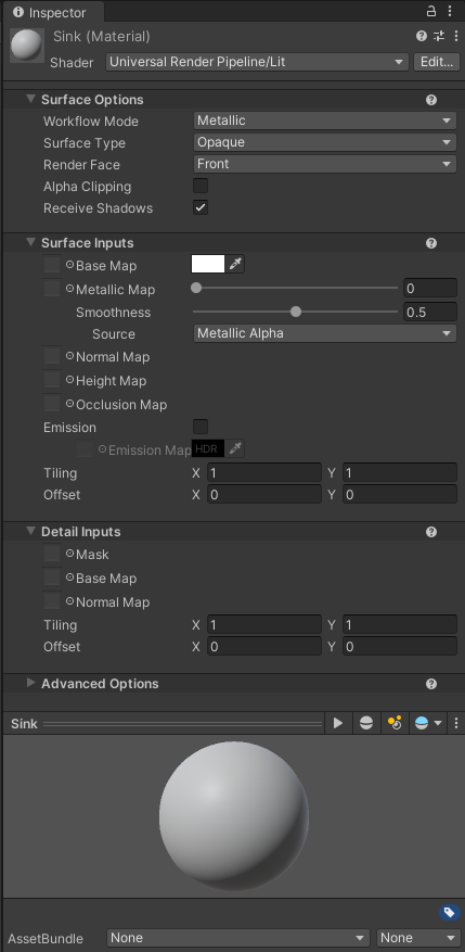
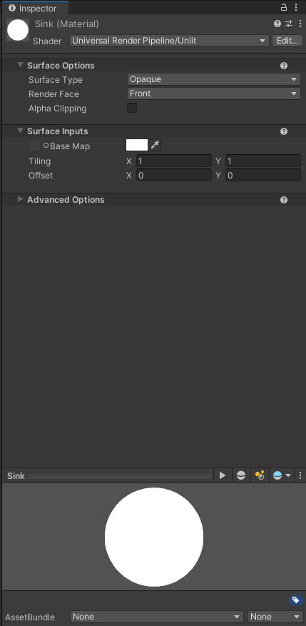
The topmost parameter Shader defines which shader is being used by the material. The shader gives the material its color and various other properties. By default, the newly created material should already be using the Shader: Universel Render Pipeline/Lit. Now, switch to the much simpler Unlit shader, by using Shader -> Universal Render Pipeline -> Unlit. The inspector should reflect this change by updating the available material properties:
Switch back to the Lit shader (using Universal Render Pipeline version) and play with the values under the Surface Inputs to see the preview change. For now, skip the Normal, Height, and Occlusion map, which will be part of a later lecture. You should get an intuitive understanding of what each of the parameters does.
You first task will be to modify the parameters of the Lit shader to make it look like something a sink could be made of - e.g., steel. You might end up with something like this:
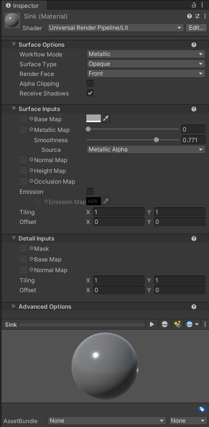
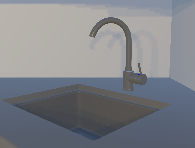
Now that we have the material created, we only need to actually use it in the scene. Select the sink, again checking under Mesh Renderer -> Element 0, press the selection circle and select the Sink material. As a side-note, you can also simply drag the material from the project window onto the model. Now you can experiment with the material further and see the effect of your changes directly on the rendered model. After you finish, you should see the sink being correctly colored:
Shader Graph and Procedural Wood
Let us now move to another problem, which is how flat and uninspiring the surfaces throughout the kitchen are. Take for example the table:
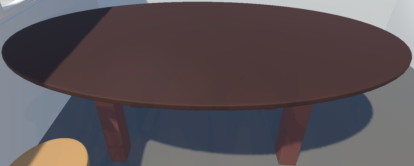
How do we fix this? We could use wood texture, mapping them onto the table by selecting the Base Map in the Lit shader. However, this would require us to make these textures in some external program first. Let us instead use the Shader Graph to create the wood grain in a procedural manner.
First, go to Assets -> Shaders -> Kitchen and create a new Shader Graph through the Create menu: Shader Graph -> URP -> Lit Shader Graph, naming it SimpleWoodSG. Double click the newly created asset and you should be greeted by the Shader Graph editor:
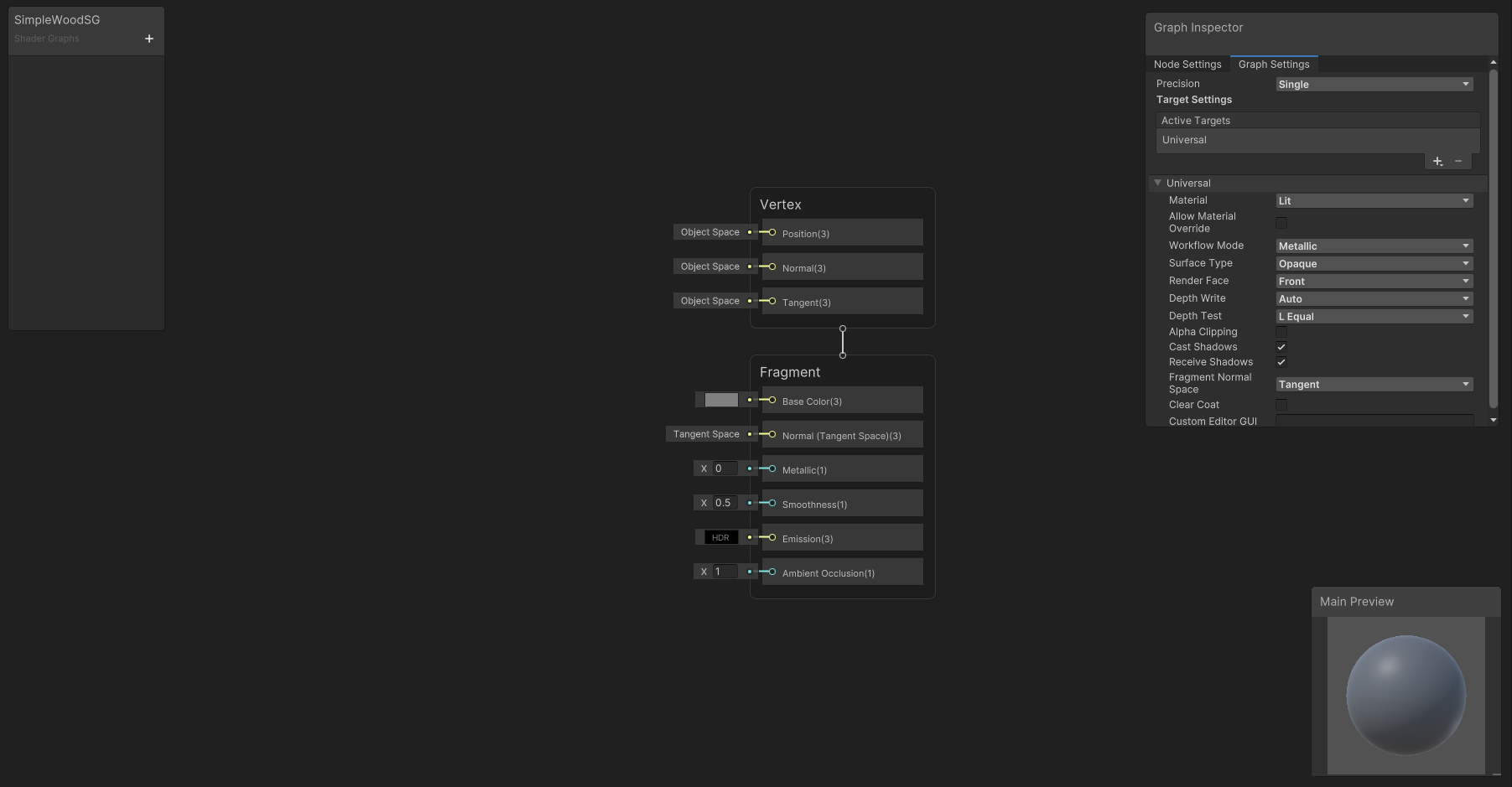
It consists of several parts. The top-left window, currently empty, displays the properties of this shader. These are useful for more complex shaders and allow modification of the material without going into the Shader Graph Editor. In the top-right, the graph inspector shows the properties of the nodes and the graph itself.
An important part in material design is its visual form, which is displayed in the bottom-left preview window. You can also try using different models through the right-click menu. If your preview is missing, then first try to enable UI Toolkit Live Reload in the three dots menu in the top right of the Shader Graph Editor. If your preview is still empty, then either is either an error with your Shader Graph or you need try to save the material to regenerate it.
Finally, the middle of the board contains the work area. It consists of nodes - operations - and edges, which facilitate the flow of data. Usually, each node has several input/output slots, which are signified by the small circles. Slots located on the left side of a node, represent the inputs, while circles on the right side are the outputs. As you can see, we already have two nodes added, thanks to choosing the Lit Shader Graph template. They represent the Vertex and the Fragment shaders.
A simplified outlook is that the Vertex shader takes the vertices of the input primitives (e.g. triangles) and transforms them into the correct position, while the Fragment shader generates the final colors. You will mostly work with the Fragment shader, but both have their uses. As you can see, the Fragment shader node has the same properties as the Lit shader we looked at earlier. Let us now use this node to modify the color of the material.
Node inputs can be modified by either connecting another nodes' output, or by directly modifying the value. Click the color selector on the left side of the Base Color property and change the color. Notice, that the material’s preview changes based on your modifications.
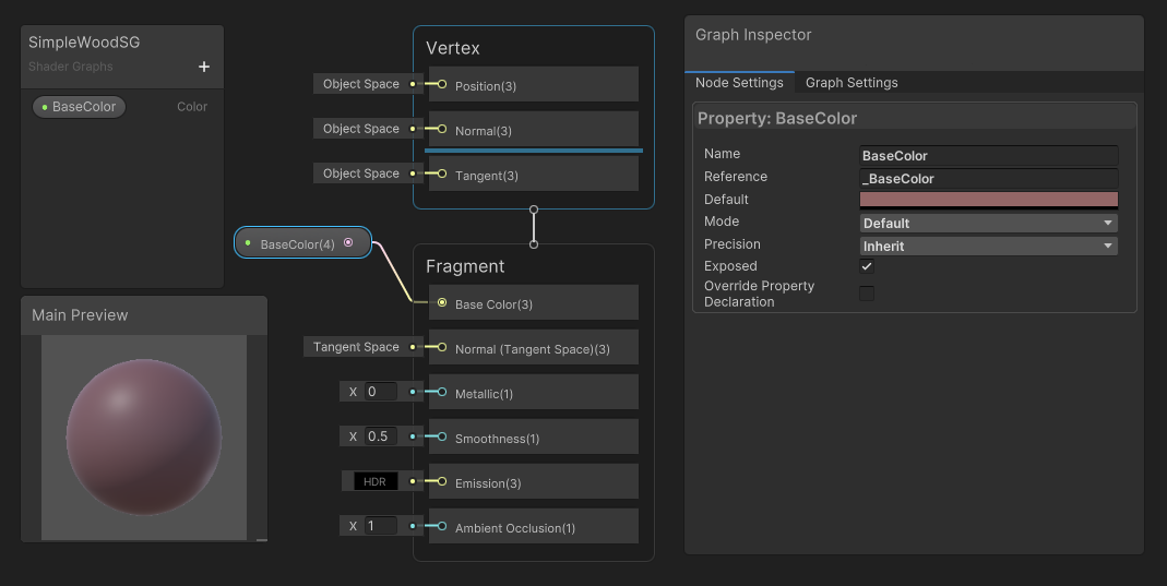
Let us start the creation of our procedural wood shader by adding the base color of the wood. Click the + in the Property Window (top left) and add a new Color, naming it BaseColor. This will allow us to modify this value from outside the Shader Graph later. Select the property and see the Node Settings in the Graph Inspector for information about the property. Modify the default color to brown. Now, drag the BaseColor property inside the working area and connect its output to the Base Color input of the Fragment node. As a result, your material preview should update to look something like this:
Now we have a base for our wood material. However, it is still rather bland and uninteresting. Let us modify it by applying additional operation through nodes. To add a new node, use the right-click menu -> Create Node, or simply press space. There are many types of nodes available, see the Shader Graph Documentation. Add a Gradient Noise node and a Multiply node, connecting them in a following configuration:
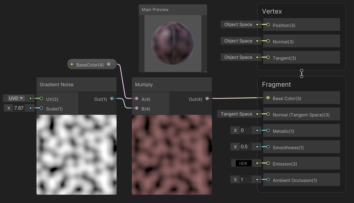
Looking at the material preview, it is definitelly not looking like wood quite yet, but we are moving in the right direction. One of the special types of nodes is the Custom Function node, which allows us to write custom code as a part of our Shader Graph. Add it now, select it and see the Graph Inspector (top right). Notice, that we can specify inputs and outputs of the node. By default, we can create a new source file and write our shader code into it. However, we can also switch the Type to String and write code directly within the inspector. We will use it to implement a simple contour shader, using the code:
float scale = 10.0;
A *= scale;
Out = smoothstep(0.0,
    0.5 + B * 0.5,
    abs(sin(A * 3.141)  + B * 2.0) *  0.5
);
Configure the Custom Function node to include two float inputs - A and B. Then add a single float
output named Out. It is important to note that the names of the input and output variables must be the
same as those actually used in the code. Finally, name the function - e.g. Contour – and copy the
provided code into the Body. The configuration should look something like this:
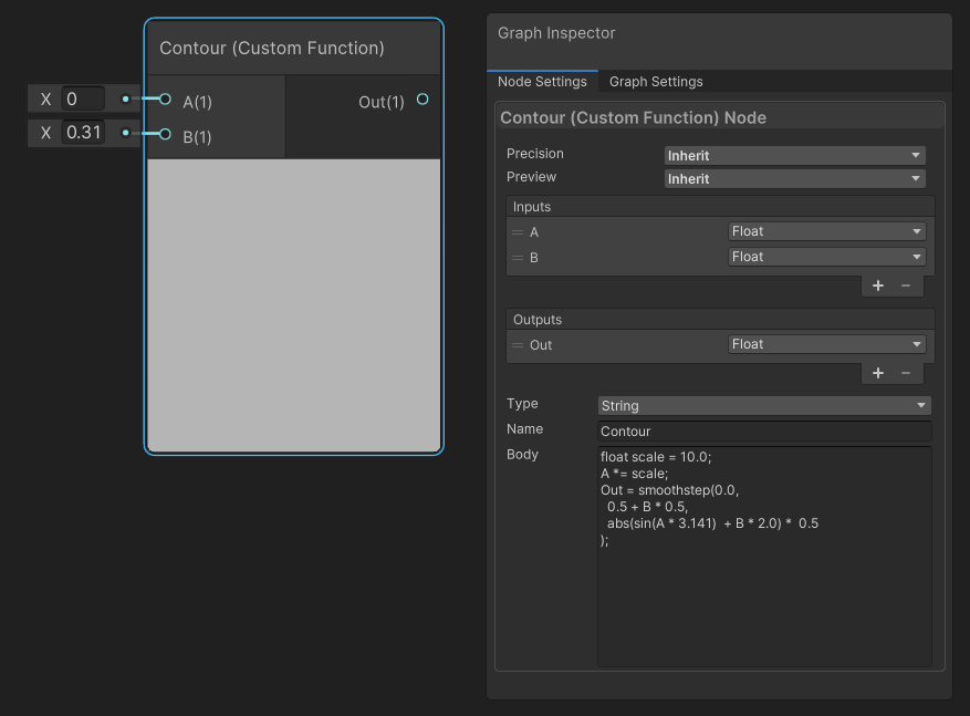 Then, connect all of our nodes sequentially as follows:
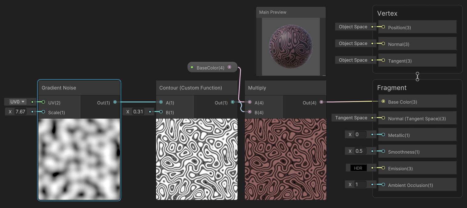
As you can see, the outputs now contain some sharper patterns, vaguely reminiscent of wood grain. Now, your second task is to complete wood material and make it look more like wood. Feel free to experiment! Get some inspiration from online resources or check the spoiler image bellow for an example solution.
Spoiler Image
Open the image in a new tab for better readability.
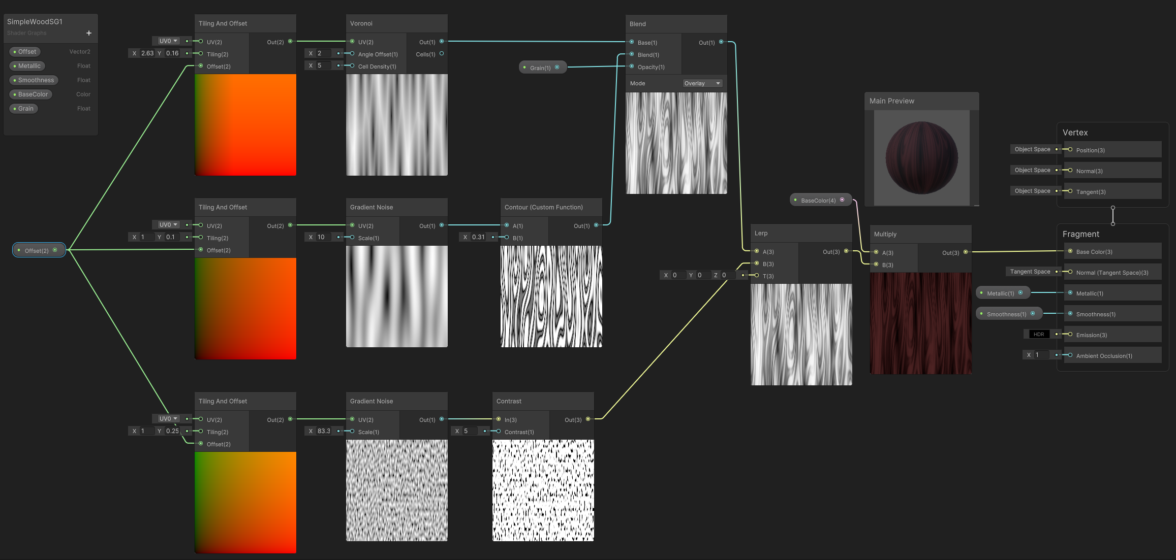
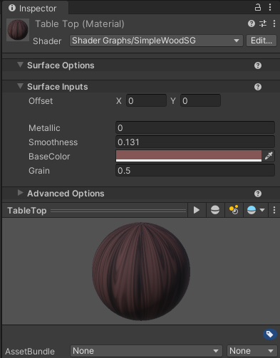
Once you are satisfied with your Shader Graph, create separate materials for the table top (TableTop) and table legs (TableLeg). Then, use our newly created Shader Graph as the Shader for the material. Notice, that we can indeed access the properties we defined through the Unity Editor:
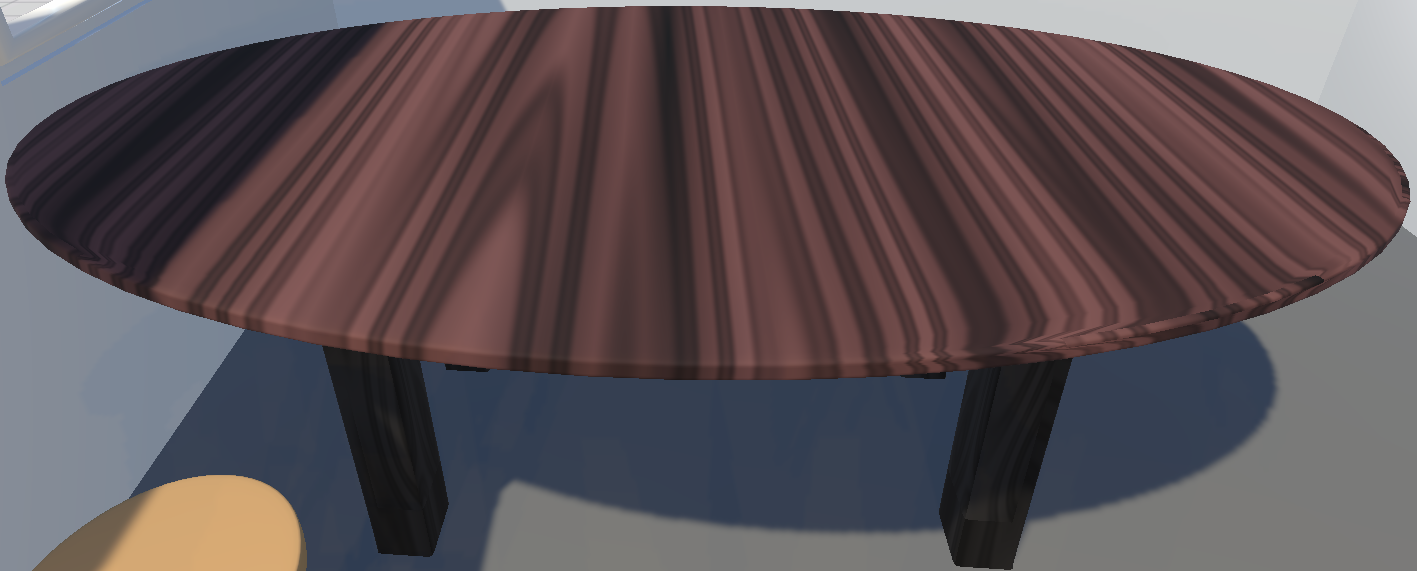
After applying it to the table model - Element 0 for the table top and Element 1 for the table legs - your table-enjoying experience should be much more satisfactory:
Personalizing the Kitchen
Your final - and most demanding - task is the personalization of the kitchen scene to your liking. Choose at least 3 materials from the Assets -> Materials -> Kitchen directory, and create a Shader Graph nicely representing the materials. Experiment with the Shader Graph and try to create materials reminiscent of the physical properties you wish the items to have. The materials do not need to be realistic: Unleash Your Imagination!.
Tips & Tricks:
- For procedural materials which are position dependant, you may use the UV node, Tiling and Offset.
- In case the UV mapping produces spatial artifacts, you can instead utilize the model’s position by using the Position Node.
Submit the Exercise
Submit the results according to the procedure detailed in the Exercise Submission chapter.
Task Checklist:
- Fix the sink material
- Implement the wood material for the table using Shader Graph
- Create at least 3 custom materials for objects of your choosing
FAQ
Following are some problems and solutions which may occur during this exercise:
- None so far!
Materials
Project Template : [zip]
Credits
Base model of the kitchen: creazilla